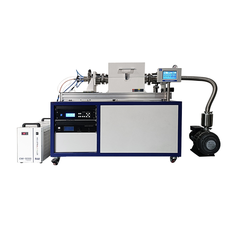
Powder magnetron sputtering coating machine can achieve the effect of uniform coating of powder surface by rotating powder in sputtering chamber. The chamber can be rotated and tilted, and the material can be discharged quickly.
Powder coating refers to putting one or more powder particles into the coating equipment to form a layer of material covering the surface of the particles through physical or chemical methods. The purpose of powder coating can be to change the properties of the particle surface, increase the stability of the particles, control the release rate of the particles, etc. This technology is an important technical means and is widely used in pharmaceuticals, cosmetics, food, agriculture and other fields.
The mechanism of powder coating mainly includes physical mechanism, assembly mechanism and penetration mechanism. The physical mechanism uses mechanical action to mix the particles and coating materials so that they adhere to the surface of the particles. The assembly mechanism is to assemble the coating materials on the particle surface through assembly technology to form a two-dimensional or three-dimensional coating structure. The penetration mechanism is through the penetration of the coating material, allowing it to enter the particle surface and form a coating structure.
In practical applications, powder coating modification equipment plays a key role. These equipment can effectively control the thickness and uniformity of the coating film, thereby improving the stability and service life of the medium. In addition, environmental equipment also plays an important role. It is mainly used to control environmental factors during the powder coating modification process, such as temperature, humidity and air pressure, to ensure that the modification process is carried out under optimal conditions.
Powder coating technology can not only change the physical and chemical properties of powder particles, such as surface functional groups, surface hydrophobicity, electrical properties, etc., but can also use adsorption, adhesion and deposition phenomena to coat the powder to achieve surface modification of the powder. Simple modification process.
In short, powder coating is an important technical means to meet the application needs in different fields by changing the surface properties of powder particles. For more information, it is recommended to consult relevant literature in the field of chemistry or consult a professional in the field of chemistry.
Rotating powder magnetron sputtering instrument uses:
1. In the field of microelectronics, rotating powder magnetron sputtering equipment is used as a non-thermal coating technology, especially suitable for materials that are difficult to grow or are not suitable for chemical vapor deposition (CVD) or metal organic chemical vapor deposition (MOCVD). Thin film deposition. It can prepare large-area and very uniform films, such as ohmic contact metal electrode films and dielectric films.
2. Rotating powder magnetron sputtering instrument also has important applications in the fields of optical films, low-emissivity glass and transparent conductive glass. For example, it can sputter to prepare SiO2 films and doped ZnO or InSn oxide (ITO) films on glass substrates or flexible substrates, so that the average light transmittance in the visible light range reaches more than 90%.
3. In the mechanical processing industry, rotating powder magnetron sputtering technology can be used to produce surface functional films, superhard films, self-lubricating films, etc., which can effectively improve surface hardness, composite toughness, wear resistance and high-temperature chemical stability. Thereby extending the service life of the coated product.
In addition, the rotating powder magnetron sputtering instrument can also be used to produce various functional films, such as films with reflection, refraction, and transmission, as well as films with absorption, polarization, etc. It is also widely used in the production of transparent conductive glass for flat panel display devices, microwave and radio frequency shielding devices and devices, and sensors.
Technical Parameters:
Device name | Rotating powder magnetron sputtering coater CY-MSP180SRF-RPM |
Characteristic | The powder material can be coated on the surface: magnetron sputtering is used. When sputtering, the powder material rolls in the cavity to achieve uniform coating on the powder surface; Can vacuum, through the atmosphere |
Basic parameter | Power supply :AC220V 50HZ Power :<1500W |
Radio frequency power supply | Input power :220V 3A Output power :0-300W Output frequency: 13.56HZ Cooling mode: The cooling mode inside the equipment is air cooling Size :444(L)*410(W)*128(H) |
Magnetic control target gun | 2-inch magnetron sputtering head (with water-cooled interlayer), connected to vacuum chamber with quick splice; Target size requirements :φ50*(≦3mm)mm thick; The 2-inch magnetron sputtering head can withstand the maximum RF power :300w; The 2-inch magnetron sputtering head can withstand the maximum DC power :500W; |
Target material | Suitable for sputtering gold, silver, aluminum, copper and other metals, less damage to the substrate and substrate temperature rise A copper target, φ2 "*3mm, is standard Target size requirement :φ2 "X(≦3mm)mm thickness |
Sputtering chamber | The sputtering chamber is a special-shaped furnace tube made of quartz glass, size: (diameter 100+ 150+ 100) ×800 (mm); The chamber can be rotated, the speed is adjustable from 1-10rpm, the speed is adjusted by the governor on the front panel, and the display screen shows the speed The two ends of the cavity are sealed by a quick connection between the magnetic fluid flanges and the stainless steel sealing flanges, and a support frame is installed at both ends of the flanges to support the magnetic fluid flanges. Remove the magnetic fluid flanges at both ends and tilt the furnace body (controlled by the knob on the front panel) to quickly discharge the material. A φ6.35 sleeve joint is installed on the left flange as the air inlet, a stainless steel needle valve controls the air inlet and a mechanical pressure gauge with a measuring range of -0.1-0.15MPa is used to observe the pressure inside the furnace; A φ19mm through-hole is used to pass the sputtering target head into the interior of the cavity A φ8m pagoda nozzle connector on the right flange is used as an air outlet, a stainless steel needle valve controls the air outlet, a KF25 connector is connected to the vacuum system, a KF16 interface is used as a backup interface, and a digital display vacuum gauge can be installed optionally. The right flange is installed with a quartz baffle in the cavity, and four stainless steel baffle bars are installed on the baffle to stir the dispersed material so that it can be fully sputtered. A guard is installed on the top of the cavity to shield the plasma, and there is a quartz observation port with a length and width of 240m at the top of the guard, which can observe the sputtering of materials. |
Heating system | The rotating quartz sputtering cavity is coated with a heating device, which can realize the heating of the rotating quartz sputtering cavity. The heating system realizes programmed temperature control through PID temperature control instrument. The maximum heating temperature allowed by chamber air tightness is 200℃. However, the temperature of the heating system can be set without this limitation, and the damage to the parts caused by operation at more than 200 ° C is not borne by the manufacturer. Temperature control accuracy :±1°C |
Vacuum system | Oil-free scroll vacuum pump; Model :CY-GWSP600, parameters are as follows: Exhaust speed :8.71/s; 31.3m3 /h Limit vacuum :1Pa Noise value: 36 LDB (A) Leakage rate (exhaust port and gas ballast valve closed):1*10-8Pa· m3 /s Maximum inlet/exhaust pressure :0.1/0.13MPa Operating temperature :5~40C Cooling method: air cooling Inlet/exhaust port size: KF40/KF16 Single-phase motor: Power 0.75kW; Voltage: ~ 115V(50Hz/60Hz); 200 ~ 230V50Hz/60Hz), two voltage options; Speed: 1425(50Hz), 1725(60Hz) rpm; Joint form: National standard, North America, Europe, UK/Ireland, India Three-phase motor: Power: 0.75kW; Voltage: 200 ~ 230 and 380 ~ 415(50Hz); Or 200 ~ 230 and 460(60Hz)V Speed :1425(50Hz), 1725(60Hz) rpm |
Water cooling equipment | Model :KJ-5000 Working current :1.4-2.1A Cooling capacity :2361Btu/h Size: 55X28X43cm(L X W X H) Tank capacity :6L Water flow rate :16L/min |
Overall dimensions of equipment | 1500mm(L)*1000mm(W)*1500mm(H) size when the shield is opened |
Weight | About 100kg |
Warranty period | 1 year (excluding wear parts such as sealing rings) |
Matters needing attention | The air pressure in the chamber shall not be higher than 0.02MPa (relative pressure) Due to the high pressure inside the cylinder, when the gas is passed into the quartz tube, the cylinder must be installed with a pressure reducing valve. In order to ensure safety, it is recommended to use a pressure lower than 0.02MPa. It is recommended to purchase a pressure reducing valve in our company. For sample heating experiments, it is not recommended to close the exhaust valve and intake valve at the flange end of the furnace tube. If it is necessary to close the air valve to heat the sample, it is necessary to always pay attention to the indicator of the pressure gauge. If the pressure indicator is greater than 0.02MPa, the air relief valve must be opened immediately to prevent accidents (such as furnace tube rupture, flanges flying out, etc.). We do not recommend customers to use flammable and explosive and toxic gases, if the customer process reasons do need to use flammable and explosive and toxic gases, please do their own relevant protection and explosion-proof measures. The company is not responsible for any problems caused by the use of flammable, explosive and toxic gases. |